It is easy and well known to connect a embedded system based on a PIC microcontoller (MCU) to a PC using the serial (RS-232) port and then write the host program on the PC. C#.net has a serial port component and is useful to read and write to and from the serial port easily. I hope you know this already and there are plenty of articles on it.
But serial port requires bulky hardware for level conversion etc (MAX232) and the data rates are not as good for a more sophisticated project with multiple sensors etc.
This is where USB comes in handy because some PIC18 MCU's come with built in with a USB controller and you only need to connect 4 wires of a USB cable to connect the device to the PC.
But unlike the serial port, writing host software to the USB port is a bit tricky. So let's take a step-by-step guide to developing a simple, but very interesting, system to communicate between a custom USB deice and a PC.
Here are the topics where we will discuss the project in detail:
Which MCU to use?
What is the device schematic?
How does it work?
What is the firmware development environment/compiler?
How to write the firmware?
How to test if the device is working?
What language to use to write the host software?
How to develop the host application?
Which MCU to use?
Even though there are plenty of MCU manufacturers, to be honest I have only know how to handle one type. Those are the PIC MCUs by Microchip. That is because in the university I was taught using PICs and it was the most wildly available and cheapest I know.
Also as I said before PIC18 series comes with built-in USB module thus it makes it easier for this type of project. Here I use the PIC18F2550 MCU.
What is the device schematic?
Our project will include the USB device with an LED. The host software on the PC will be able to switch ON and OFF the led and the host software will also be able to read the LED state. The circuit arrangement for this device is shown below.

Find the following components for the project
PIC18F2550 microcontroller
20MHz crystal oscillator
470nF capacitor
an LED
330Ohm resistor
10k resistor
spare USB cable
Cut off the female end of the cable (NOT THE SIDE THAT CONNECTS TO THE PC) and peal off some length(about 4cm) of the insulator. There must be four wires in the cable. Now solder some firm wires pieces to the four cable wires so that the cable wires cab be easily fixed on to the breadboard.
Take care when connecting the USB wires to the MCU because wrong connections may damage the PC USB host or the MCU itself.
A USB male connector looks like the following, when seen from the front.

Starting from right
1 - (+)
2 - D-
3 - D+
4 - (-)
D+ and D- are the data lines, (+) is the +5V line and the (-) is the ground line.
In the circuit diagram pins 15 and 16 of the MCU are as follows
pin 15 --------- D-
pin 16 --------- D+
And I guess you can understand the rest of the pin connections. The pinout diagram of the PIC18F2550 MCU is shown below

My USB cable had the four wires in four colours.
How does it work?
There are many USB device types. Some of them are modems, printers/faxes, cameras/video devices, HID(mouse, keyboard) etc. To communicate with each of these device types the Operating System(OS) uses different protocols. A device manufacturer must provide the device drivers for his device. For example a web camera manufacturer must provide drivers for the OS to recognize his device as a web camera and act accordingly. And as you might understand writing device drivers is no easy task.
But fortunately the HID(Human Interface Device) class of devices do not need drivers. HID devices include keyboards and mice and the OS comes with the drivers for HID so the user does not need to install drivers for his USB keyboard and mouse.
This is a point which we exploit for our advantage. That is we design our device(probably a data acquisition, DAQ, device) as a HID device so that we do not require to write our own drivers.
Our USB device must include a descriptor which will tell the OS that the device is of type HID and what the data speed and data packet (report) size will be and so on.
That will be what happens when you plug in your device, the OS will detect the device and if it is HID apply the default driver or else look for the driver of the relevant device class.
After that we cane start USB communication, that is to read and write from the device, from the PC.
What is the firmware development environment/compiler?
First of all we should program the MCU to act as a USB/HID device. For this we have to use a MCU programming language to write the program and a compiler to compile the source file into a .HEX file, which will be used to program the MCU. If you are not aware of PIC programming I recommend learning it first, but for this project itself it is not a must as everything is provided, but if you want to develop this further, it will be important that you know what's going on.
Also we need a development environment to make it easy for us to write our code and to compile. That is we need a Graphical User Interface(GUI) that will allow us to create projects at the click of a mouse, and it should highlight our code and should allow us to compile the project easily to generate the HEX file.
A software program that includes both a code editor and the compiler is called an Integrated development Environment(IDE)
There are several programming languages and IDEs, let's see what they are and their pros and cons

As seen MPLAB IDE and the assembly language is the free option, but when it comes to programming something as complex as USB, even I don't know how to do it. And there is very little documentation known to me. Since I have a Full MikroC IDE I use it here. I hope you have it too and else you should use this article as a guide and find your self how to write the firmware in assembly.
As said earlier you need MikroC IDE to write this code. Open a new project in mikroC IDE.
In the New project wizard chose the following settings
CPU - PIC18F2550
Clock - 48MHz
and set the following configuration bits, by ticking the check boxes. (The exact flag name may vary depending on the MikroC version, but will be similar and easy to find)
PLLDIV_2_1L
CPUDIV_OSC1_PLL2_1L
USBDIV_2_1L
FOSC_HSPLL_HS_1H
FCMEM_OFF_1H
IESO_OFF_1H
PWRT_ON_2L
BOR_ON_2L
BORV_43_2L
VREGEN_ON_2L
WDT_OFF_2H
WDTPS_256_2H
MCLRE_ON_3H
LPT1OSC_OFF_3H
PBADEN_OFF_3H
CCP2MX_ON_3H
STVREN_ON_4L
LVP_OFF_4L
ICPRT_OFF_4L
XINST_OFF_4L
DEBUG_OFF_4L
CPUDIV_OSC1_PLL2_1L
USBDIV_2_1L
FOSC_HSPLL_HS_1H
FCMEM_OFF_1H
IESO_OFF_1H
PWRT_ON_2L
BOR_ON_2L
BORV_43_2L
VREGEN_ON_2L
WDT_OFF_2H
WDTPS_256_2H
MCLRE_ON_3H
LPT1OSC_OFF_3H
PBADEN_OFF_3H
CCP2MX_ON_3H
STVREN_ON_4L
LVP_OFF_4L
ICPRT_OFF_4L
XINST_OFF_4L
DEBUG_OFF_4L
- Now go to the mikroC installation directory and follow this path Mikroelektronika-->mikroC-->Examples-->EasyPic4-->extra_examples-->HID-library
- Here find the two C/C++ header files Definit and VARs, copy them and paste them into your project folder.
- Now in the MikroC IDE go to Tools-->HID Terminal, and it will open a dialog, select its Descriptor tab and then it will look as follows.
The device supports three commands. They are
on--
off-
read
Each command is four characters in length for now, but this can be changed later.
- on-- command sitch the LED, ON and echo the same command back
- off- command switch the LED, OFF and echo the same command back
- read command reads the current state of the LED and echoes the response as read -OFF if the LED is OFF or as read--ON if it is ON.
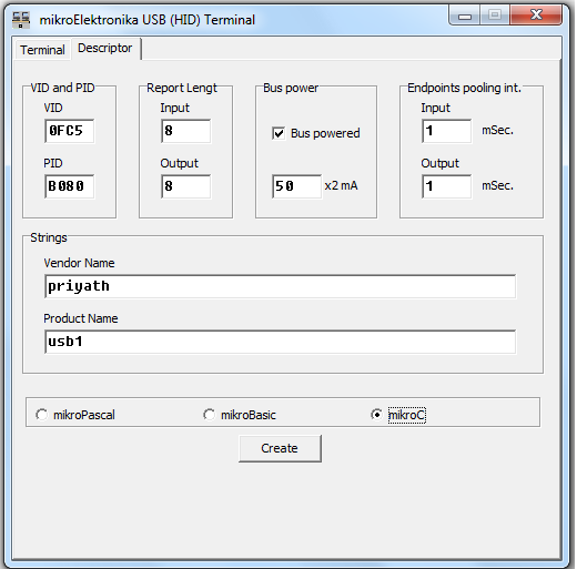
- Fill in the fields as, VID=0FC5 PID=B080 input=output=8, vendor name=priyath(can be your name), product name=usb1(can be anything)
- IMPORTANT: VID and PID are allocated by the USB regulatory body and must be purchased. For testing purposes this is acceptable, but cannot be used for commercial use without a legal VID and PID.
- PID and VID is used to distinguish your device from the host software. It is important to remember your PID and VID, if you use different ones than used here.
- Now select mikroC radio button at the bottom and press Create button.
- Save the file in your project directory with any name with the extension (.c), <any_name>.c In my case I saved it as usb1Desc.c
- Now go to Project-->Add To Project and select usb1Desc.c
- usb1Desc.c is the descriptor file that tells the PC OS that our device is a HID type device and how to do the communication. MikroC makes it easy to generate the descriptor file. I'm yet to figure out how to generate the descriptor without mikroC
- Now in a new C file type the following code and save it
unsigned short m, k;
char cnt;
unsigned short userRD_buffer[8] absolute 0x280;
unsigned short userWR_buffer[8] absolute 0x2c0;
void interrupt() {
asm CALL _Hid_InterruptProc
asm nop
}//~
void init()
{
// Ports Configuration
TRISA = 0;
PORTA=0;
}
void echo_cmd()
{
for(m=0;m<8;m++)
{
if(m<4)
userWR_buffer[m]=userRD_buffer[m];
if(m>3)
userWR_buffer[m]='1';
}
}
void read() //set the LED status to the lower 4bytes
{
if(PORTA.F0==1)
{
userWR_buffer[4]='-';
userWR_buffer[5]='-';
userWR_buffer[6]='O';
userWR_buffer[7]='N';
}
else if(PORTA.F0==0)
{
userWR_buffer[4]='-';
userWR_buffer[5]='O';
userWR_buffer[6]='F';
userWR_buffer[7]='F';
}
}
/** Main Program Routine **/
void main(void) {
init();
Hid_Enable(&userRD_buffer, &userWR_buffer);
while(1)
{
while(!HID_Read());
if(userRD_buffer[0]=='o'&&userRD_buffer[1]=='n'&&userRD_buffer[2]=='-'&&userRD_buffer[3]=='-')
{
PORTA.F0=1;
echo_cmd();
while(!HID_Write(&userWR_buffer,8));
}
else if(userRD_buffer[0]=='o'&&userRD_buffer[1]=='f'&&userRD_buffer[2]=='f'&&userRD_buffer[3]=='-')
{
PORTA.F0=0;
echo_cmd();
while(!HID_Write(&userWR_buffer,8));
}
else if(userRD_buffer[0]=='r'&&userRD_buffer[1]=='e'&&userRD_buffer[2]=='a'&&userRD_buffer[3]=='d')
{
echo_cmd();
read();
while(!HID_Write(&userWR_buffer,8));
}
else
{
echo_cmd();
while(!HID_Write(&userWR_buffer,8));
}
}
}//~!
The LED is connected to PORTA0 and PORTA is set as an o/p and initially PORTA is all low. (logic 0)
TRISA = 0;
PORTA=0;
PORTA=0;
Two arrays of type short with size 8 is used to read the i/p command and to store the o/p respomse
userRD_buffer[8]
userWR_buffer[8]
In our system only the lower four bits are used for the command and response. The other four bits are used to send/recive additional data.
The line of code while(!HID_Write(&userWR_buffer,8)); writes the 8bit long response stored in userWR_buffer
The line while(!HID_Read()); reads incoming command and stores it in the 8bit userRD_buffer
The MCU runs an infinite while loop, continuously listening for incoming commands.
And I hope the rest of the code is understandable.
After typing the above code save it and go to Project-->Build. If everything is OK, success message should appear. If a message such as Demo limit appear that means your mikroC is a demo version and you need to purchase a license key. Otherwise a HEX file should be generated in your project directory.
Now we need to program our MCU wit the HEX file. I use a USB PIC programmer, so I connect the programmer to the PC, mount the PIC MCU on to the ZIF socket and load the HEX file. ( If you are confused here, don't worry prepare the basic needs to program a PIC microcontroller and do a LED blinking project first then come back)
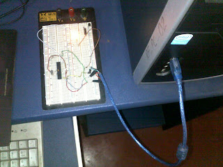
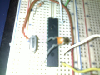
Now I program the MCU and place it in the correct orientation on the bread board.
How to test if the device is working?
Now that all is ready, with the MCU programmed and the circuit in place, connect the USB cable to the PC. If everything is working fine the OS should respond to a new device plugged in. A ballon should appear at the taskbar indicating the status. If your device hasn't been programmed correctly an error message saying not detected should appear, else you should get a message like , device successfully installed.
Go to Device Manager and under "Human Interface Devices" you should see the device

Click properties-->Details and chose Hardware Ids and that will show us our VID and PID in a string.

Now that our hardware has been detected we can test if it is responding to our commands.

How to test if the device is working?
To test the HIS USB communication, we can use the same tool we used to create the Descriptor, in MikroC. This time go to the Terminal tab and select your device.(It should appear in the device list)
Now type a command on-- and press Send button to see the LED lights up. If it does, ONLY HALF OUR JOB IS DONE................................................
How to develop the host application?
The host application is written in C#.Net. I modified a sample application provided my microchip to get USB communication. There are many USB APIs, some are trial versions, some lack help. This one doesn't require any driver installations.
The API functions are described in the program file itself. The basic USB operations are identifying the device plugin, removal, reading and writing commands.
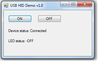
The sample application toggles a LED. There are two buttons for this purpose. ON sends the --on command to the MCU. Button OFF sends the -off command to the MCU. As described earlier the MCU does the corresponding action depending on the command.
Also the read command is sent in intervals of 500mili seconds and its response is read. read command will give the response --ON if the LED is on or -OFF if the LED is off.
The application uses three threads. One thread is the Form thread which is the GUI which interacts with the user. Another thread is the ON/OFF thread which sends the --on and -off commands depending on the button press. The other thread sends the read command if a boolean variable is set to true. This variable is set by a Time which elapses at 500ms intervals.
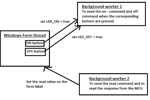
Threads are used so that the Form will not get stuck.
Here is the he C# project file, and I hope you will understand how it works and will be able to modify it to suit your needs.
Thank you.
PS: Please be kind enough to leave a comment saying whether you liked it or not. All positive and negative comments are welcome.
How to develop the host application?
The host application is written in C#.Net. I modified a sample application provided my microchip to get USB communication. There are many USB APIs, some are trial versions, some lack help. This one doesn't require any driver installations.
The API functions are described in the program file itself. The basic USB operations are identifying the device plugin, removal, reading and writing commands.
The sample application toggles a LED. There are two buttons for this purpose. ON sends the --on command to the MCU. Button OFF sends the -off command to the MCU. As described earlier the MCU does the corresponding action depending on the command.
Also the read command is sent in intervals of 500mili seconds and its response is read. read command will give the response --ON if the LED is on or -OFF if the LED is off.
The application uses three threads. One thread is the Form thread which is the GUI which interacts with the user. Another thread is the ON/OFF thread which sends the --on and -off commands depending on the button press. The other thread sends the read command if a boolean variable is set to true. This variable is set by a Time which elapses at 500ms intervals.

Threads are used so that the Form will not get stuck.
Here is the he C# project file, and I hope you will understand how it works and will be able to modify it to suit your needs.


Thank you.
PS: Please be kind enough to leave a comment saying whether you liked it or not. All positive and negative comments are welcome.
The letter W represents watt which is the unit of power. The higher the wattage, the more power the bulb will use. Since led umbrella lights are already very bright, a 35W bulb is sufficient and gives greater illumination than a conventional halogen bulb of 55W.
ReplyDeleteGreat project, you C# download link is broken... can you fix?
ReplyDelete@Rando Thank you for your interest in my project. I am sorry I have lost all my project files since I formatted my PC several times after the project and couldn't burn it on to a CD. But I can say the fundamental of USB HID communication between a windows application and the device is windows events. In C# you get the WndProc event. When you plug in a USB device the application gets a event code. You check if the event is related to USB HID class and if so you proceed. After detecting the USB device the next step is to read and write from the device.
DeleteI'm not an expert on this and I just modified some source code I found in the internet.
This link leads to a good post on this subject
http://www.waitingforfriday.com/index.php/Open_Source_Framework_for_USB_Generic_HID_devices_based_on_the_PIC18F_and_Windows
Unfortunately with the work that I have I do not have time for these kind of projects. But if you have time I recommend you spend it on this testing and developing the application.
Could you upload the VB source code now? please.
ReplyDeleteThere is a good USB HID API @ http://simplehidlibrary.codeplex.com/
ReplyDeleteI will try to develop an application using it. You may also try it as an API will make it easier for application development.
I coded the program using mikroc pro for pic and that i cannot see the name of the product in the hid terminal that is the name that I gave in descriptor file is not shown in the hid terminal when the device is connected.. what is the solution for it.. pls reply
ReplyDeleteDear Kumari
DeleteCheck you did the following
1) include the usb1Desc.c in the project before compiling.
2) set the configuration bits properly
3) did your wiring properly (check your circuit again)
It is sometime back that I did this. I also succeeded after a lot of trials and errors. keep trying
In hid terminal, i get only the pickit2 programmer and i cannot detect the device name in hid terminal. I tried many times i could not get the device detected.
Deletehello, I tried to rebuilt your project
ReplyDeletefirst windows does not recognize the device, so i rebuilt the circuitry and the host does not detect the device
can you give me a clear schematic or advises to resolve this.
thanks in advance
Super! Thanks :)
ReplyDeletehttp://fs10n4.sendspace.com/dl/0852d94ed1b2851fe916b1e8e3b2adab/4ecb47e4437e346c/tun5te/HID%20test.zip
ReplyDeleteC# link app not work
Supperb ! Thanks
ReplyDeletehttp://www.developerfusion.com/article/84338/making-usb-c-friendly/
ReplyDelete